A couple of months ago I was reading up on Unreal Engine 4 and I came across the term physically based rendering. At first I couldn’t get a clear understanding as every article regarding PBR just gets straight into the details and compares the different mathematical formulas and no one just came out and explained the basics. Later on I found this course and decided to write a little DirectX 11 sample implementing the techniques from this course so that I can fully understand physically based rendering.
So PBR … what is it? And what makes it so much better?
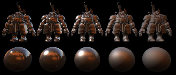
PBR basically replaces the current Blinn/Phong lighting model with a model that allows artists and developers to more accurately simulate real world lighting. Where the current Blinn/Phong model was created by trying to make games look great with the least expensive calculations and forsaking accuracy, PBR is a step towards realistic simulation of lighting. PBR is still an approximation but is a big step closer to realistic lighting.
Physically based rendering is a guideline and what it boils down to is that it uses Bidirectional Reflectance Distribution Functions or BRDFs to calculate diffuse and specular lighting. These BRDFs can be found around the web and it is up to the developer to decide which ones to implement: So in layman’s terms, the only change to your shaders are that the standard lighting equations you’re used to:
// Diffuse Lighting
float ndotv = dot(normalWS, directionToLightWS);
float4 diffuseLighting = LightColor * ndotv;// Specular Lighting
float rdotv = dot(reflectionVecWS, normalWS);
float4 specularLighting = (SpecularIntensity * pow(rdotv, SpecularPower)) * SpecularIntensity;
are going to be replaced by four BRDF functions, and these BRDFs define how the light will bounce or refract off of the surface of the object:
// Diffuse Lighting
float4 directLightingDiffuse = DirectDiffuseBRDF(…);
float4 directLightingSpecular = DirectSpecularBRDF(…);// Specular Lighting
float4 indirectLightingDiffuse = IndirectDiffuseBRDF(…);
float4 indirectLightingSpecular = IndirectSpecularBRDF(…);
Now there are a set of general BRDFs (that I’ll explain below) which should be sufficient for most of your needs as they allow you to easily specify the parameters of the lighting model that determine how light is reflected and refracted off of the surface of an object. This is of a great benefit to artists as lighting behaves consistently and there is no need to create numerous textures for each type of surface as you can just have a set of presets for each surface type and an artist can select whether a surface is leather, plastic, metal, bricks etc. and the BDRF will handle the rest.
Direct Lighting BRDFs
Direct Diffuse:
From everything I’ve read it seems that the Lambert BRDF is the best choice for direct diffuse lighting. There are a couple of alternatives but general consensus is that they don’t add enough value to make their increased complexity worthwhile. The Lambert BRDF is pretty straight forward to implement and it results in a really smooth falloff. Its implementation is literally:
float3 diffuseLightingFactor = (LightColor * nDotL) / Pi;
You can find more detail here.
Direct Specular:
For specular lighting, every single article I came across uses the Cook/Torrence Microfacet BRDF. A microfacet BRDF assumes the surface of an object is made up of microfacets or tiny mirrors that reflect incoming light around the normal. For this BRDF we’re dropping the normal parameters SpecularIntensity and SpecularPower and introducing two new parameters:
Metalness
Determines how metallic vs dielectric and object appears. It’s not the same as the specularity we’re used to, but basically determines how shiny and reflective an object appears.
Roughness
Determines how smooth the surface of the object appears. The lower the roughes, the more all the facets on the surface are aligned and the reflection appears crisper, whilst the rougher the surface, the more those facets are randomly orientated and the reflection is scattered.
In order to implement this BRDF we need to solve the following equation:
f = D * F * G / (4 * (N.L) * (N.V))
Where
D: Normal Distribution
It computes the distribution of the microfacets for the shaded surface.
F: Fresnel
It describes how light reflects and refracts at the intersection of two different media (most often in computer graphics its air and the shaded surface).
G: Geometry shadowing term
Defines the shadowing from the microfacets.
Now these are a couple of formulas to solve these terms, but generally the ones that seem to be the most used are:
D: Trowbridge-Reitz/GGX
F: Schlick’s approximation
G: Smith’s approximation
Brian Karis from Epic Games has a great article comparing each formula which you can find here.
The guys at ReadyAtDawn studios (makers of The Order 1886) have also uploaded the shader code for us for the specular microfacet BRDF which you can find here. Or you can download the sample at the bottom of the post.
Indirect Lighting and Image Based Ligthing
Indirect lighting is a little trickier as we need to use a technique called Image Based Lighting (IBL), which basically pre-calculates the lighting from an environment map assuming that you’re always in the center of the environment. Trying to simulate indirect lighting in real-time is just too expensive as you basically have to treat each pixel in the environment map as a light source and calculate the incident lighting for a particular surface pixel taking all these light sources into account. So this is where image based lighting comes in.
Indirect Diffuse (Irradiance Environment Mapping):
For diffuse lighting you use a technique called irradiance environment mapping, where you generate an irradiance map by sampling an environment map literally hundreds of thousands of times to calculate the indirect light from each direction. Luckily we can use Spherical Harmonics to optimize this process. Using 2nd order spherical harmonics you can encode all the low frequency lighting from the environment map into only 9 coefficients.
The whole process is explained within the following article. I however was just lazy and used Sebastien Lagarde’s modified version of AMD’s CubemapGen to generate an irradiance map, you can find the tool on his blog here. Once you have the irradiance map all you have to do is sample it using your surface normal and multiply it with the diffuse albedo in order to get the indirect diffuse lighting:
float4 indirectDiffuseLighting = irradianceMap.SampleLevel(SamplerAnisotropic, normalWS, 0) * diffuseAlbedo;
We used this technique in our game Death Lazer that we created for Microsoft’s Dream Build play competition two years ago, so I’ll update this sample in the future with a implementation of how to generate irradiance maps … after I’m done playing Bloodborne 🙂
Indirect Specular:
For indirect specular lighting you again have to sample all the pixels in an environment map and generate a Pre-filtered Mip-Mapped Radiance Environment Map or PMREM. What this map basically does is pre-calculates the radiance for us and encodes it into a cubemap which can then be sampled using the normal of the pixel, very much the same as the irradiance map. Now you would have noticed if you used Sebastien Lagarde’s Modfied CubemapGen that it supports generating PMREM cubemaps. The tool however was built for a last gen game called ‘Remember Me’ and only allows you to select either a Phong or Blinn BRDF, not the Cook/Torrence microfacet. So we need to use a technique provided by Brian Karis from Epic Games which you can find here.
Epic use a split sum approximation to generate a PMREM and a separate BRDF integration map (2D LUT) which can be used to integrate any BRDF with the PMREM. I’m not going to go through all the code and explain everything in detail as it is implemented in the sample at the end of the article, but two things to note is that in order to generate the PMREM we are again going to be sampling the environment map hundreds of thousands of times again, Epic Games however has optimised this by using a technique called Importance Sampling. Importance Sampling basically splits the environment map into sections and samples important sections (sections with brighter pixels) more than other sections in order to reduce the number of samples needed.
Secondly, in order to solve the problem of storing the incoming radiance for any roughness, we store the radiance for higher roughness levels into the mip maps of the cubemap. So this way if you have a 256×256 radiance map, you’ll have 7 mip maps (0: 256×256, 1: 128×128, 2: 64×64, 3: 32×32, 4: 16×16, 5: 8×8, 6: 4×4) and you’ll write the lowest roughness (0) to the first mip map and the highest roughness (1) to the last mip map and so forth. Now this took a little while to get figured out as I come from a XNA and Unity3D background and haven’t touched C++ or DirectX for a very long time. I just couldn’t get a clear picture of how to access the mip maps in a Texture2DArray. In the end it was actually quite simple and I was just over complicating it for myself, trying to use DirectX sub resources and other complex structures 😉
To download the sample click here.
Just on a side note, as I mentioned I don’t come from a C++ coding background so I’m sure my code isn’t the best.


Thankyou very much for your topic! Very helpful for me!
This blog post has immensely help me so much. I think your the only person who has made a tutorial with a sample on PBR for DirectX 11. I have had a small problem though which I posted on stackoverflow http://gamedev.stackexchange.com/questions/130099/physically-based-rendering-in-directx . If you do see this comment it would be great if you could help me :).
I think you have a mistake in your “old” specular formula… you need light color.